
ShapeScan workflow
Tutorial
Print the correct marker sheet, photograph the object cleanly, review the overlay, edit the contour if needed, then export true-scale SVG, DXF, STL or STEP.
5 minute setup
Quick start
- Print the matching marker sheet at 100% / Actual size.
- Measure one marker edge-to-edge and confirm it matches the sheet spec.
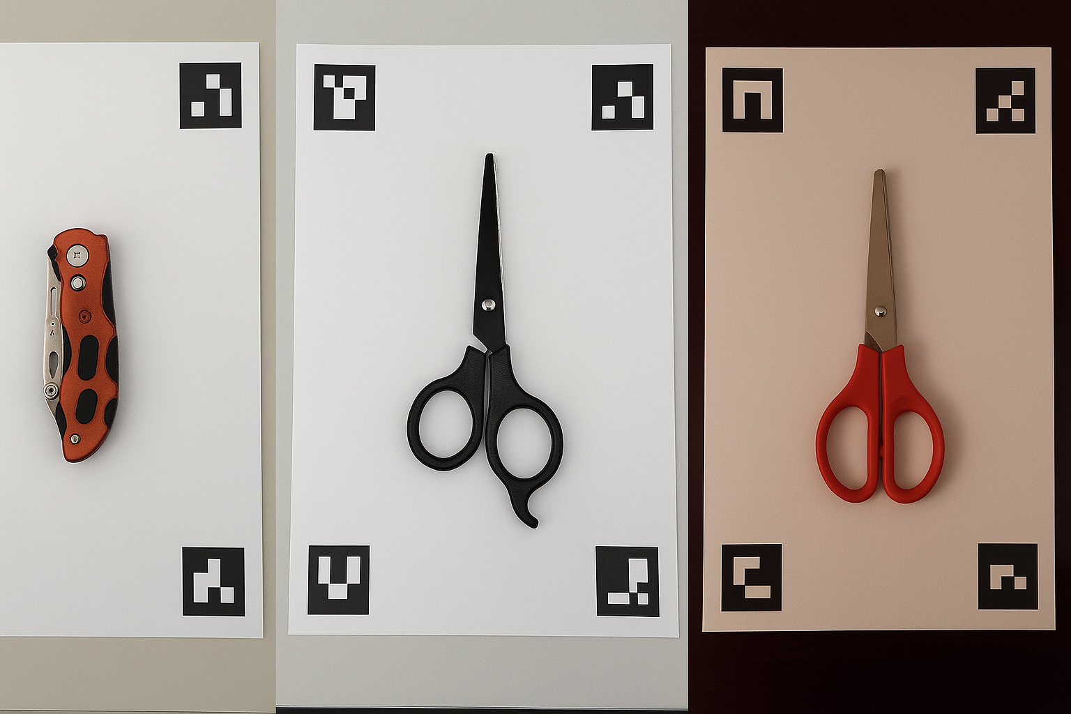
- Place the object flat inside the markers, with every marker visible.
- Take a sharp, perpendicular photo with soft light.
- Upload, inspect the overlay, edit the contour if needed, then export.
True scale
Use the right marker sheet
The markers define the physical scale. If the sheet is printed with scaling, every export will inherit that scale error.
- Always choose 100% / Actual size in the print dialog.
- Do not use Fit to page, Scale to fit or borderless auto-scaling.
- Use the sheet that matches the scan area you need: A5, A4, A3, 2x A4, Half Letter, US Letter, Tabloid or 2x Letter.
- Keep all sheet markers visible, sharp and uncovered.
Expected marker dimensions
Measure the outside of the black square, including its black border. Do not include the white margin. Check both width and height after printing at 100%.
| Marker sheet | Black square | Scan area |
|---|---|---|
| A5 | 25 × 25 mm | 148 × 210 mm |
| A4 | 30 × 30 mm | 210 × 297 mm |
| A3 | 35 × 35 mm | 297 × 420 mm |
| Half Letter | 25 × 25 mm | 139.7 × 215.9 mm |
| US Letter | 30 × 30 mm | 215.9 × 279.4 mm |
| Tabloid | 35 × 35 mm | 279.4 × 431.8 mm |
| 2 × A4 vertical | 30 × 30 mm | 210 × 594 mm |
| 2 × A4 horizontal | 30 × 30 mm | 420 × 297 mm |
| 2 × Letter vertical | 30 × 30 mm | 215.9 × 558.8 mm |
| 2 × Letter horizontal | 30 × 30 mm | 431.8 × 279.4 mm |
If your measured size differs, reprint at actual size or enter the measured marker size in the scan settings.
Capture quality
Take a photo the model can trust
ShapeScan corrects lens distortion and perspective, but the input still matters. The best captures are flat, sharp and evenly lit.
- Hold the phone as perpendicular to the sheet as possible.
- Center the sheet in the frame and keep the full sheet visible.
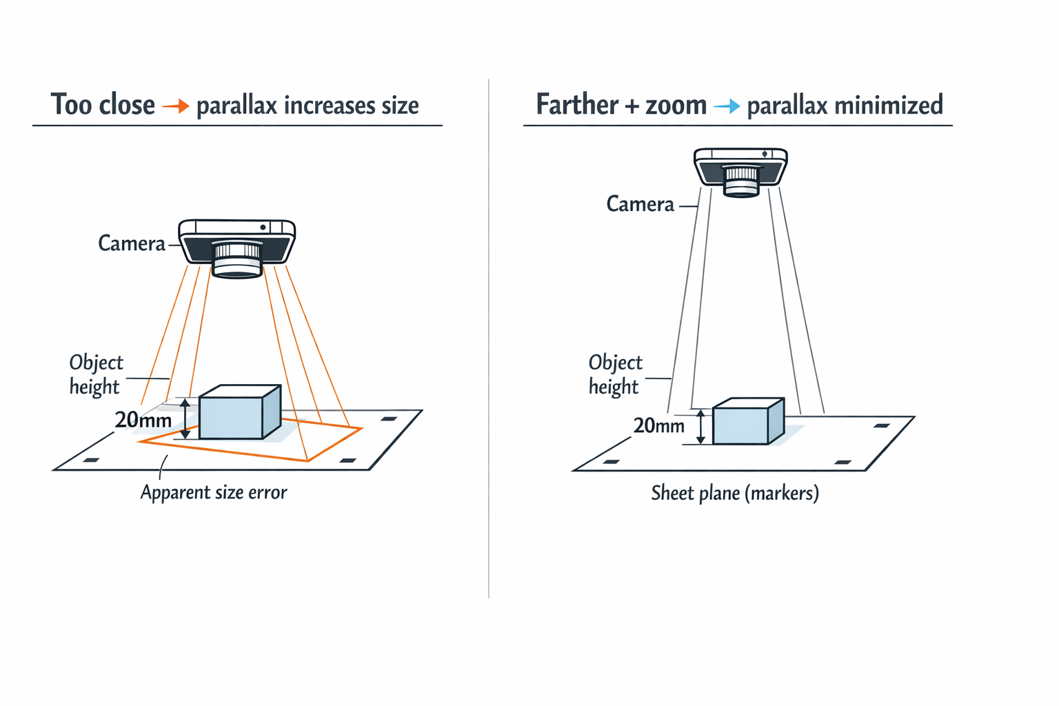
- Avoid ultra-wide lenses. Use the normal lens or step back with 2x optical zoom.
- Use soft light. Flash is allowed, but strong shadows and reflections may need manual cleanup.
- For tall objects, shoot from farther away to reduce parallax.
v 2.2.0 Multi-object
Scanning more than one object
Premium users and beta testers use v 2.2.0 Multi-object by default. The workflow finds separated objects on the sheet, crops each object, runs the high-quality single-object segmentation on each crop, then recombines the true-scale outputs.
- Leave clear paper space between objects so they can be separated.
- Do not let objects touch markers or overlap each other.
- Use Keep internal holes when the objects have cutouts you need in CAD.
- On the results page, inspect the full overlay and each object export before using the files.
Multi-object is designed to preserve the same outline quality as the current single-object workflow. Very thin, low-contrast or touching objects may still need the editor.
Upload settings
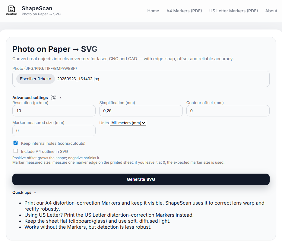
Options that change the result
- Keep internal holes
- Keeps holes and cutouts as separate paths in SVG/DXF/STL/STEP.
- Simplification
- Lower values keep more detail. Higher values smooth noisy edges.
- Contour offset
- Positive grows the outline. Negative shrinks it. Use it for fit, kerf or parallax correction.
- Marker measured size
- Use this only if your printed marker is not the nominal size, but you still want accurate scale.
- Export preset
- Changes export compatibility for CAD/CAM workflows. It does not change object detection.
Manual correction
Use the editor when the outline needs finishing
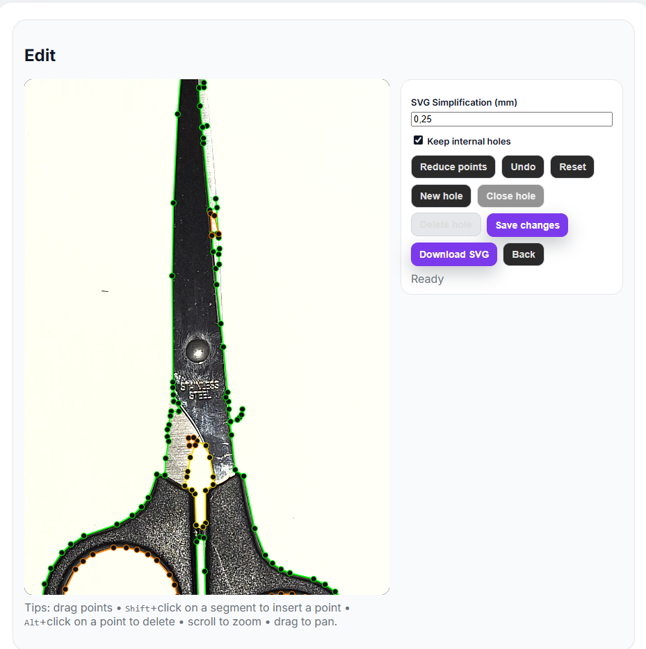
The editor is for final control. You can move points, add points, delete points, measure the real size, create holes, offset the contour and export the corrected geometry.
- Select moves existing points.
- Add inserts contour points where more detail is needed.
- Hole creates an internal cutout path.
- Measure checks dimensions before export.
- Clean contour removes tiny spikes, duplicate points and self-intersection noise where possible. If the contour is already clean, it may look unchanged.
- Geometry check reports dimensions, point count and contour problems before you export.
Results
Inspect before using the file
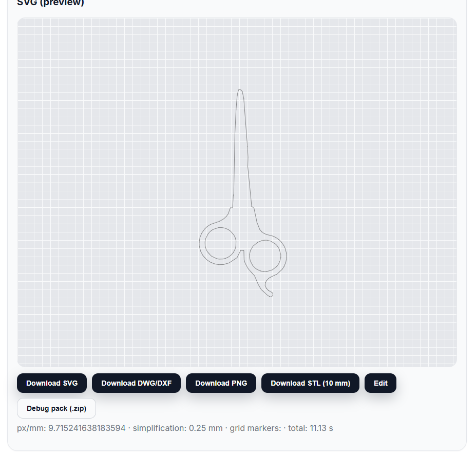
The overlay is the fastest way to judge whether the export is usable. If the green outline follows the object edge, download the format you need. If not, open Edit and correct it.
- SVG is best for laser, CNC import and vector editing.
- DXF is best for many CAD/CAM tools.
- STL and STEP create a 10 mm solid from the outline.
- PNG/mask files are useful for debugging or visual comparison.
Troubleshooting
Common problems and fixes
Use the official sheet, keep all markers visible, avoid blur, and do not cover marker corners.
Reprint at 100% and measure a marker. If needed, enter the measured marker size before processing.
Enable Keep internal holes and make sure the hole has enough contrast against the sheet.
Use softer light, move the light source, or clean the edge in the editor.
Increase spacing between objects, improve contrast, and keep thin objects away from similar-colored backgrounds.
Align or rotate the imported SVG before reading X/Y bounding boxes. A slightly tilted long object can show a larger axis-aligned box.
Final check
Before export
- Correct sheet and 100% print scale.
- All markers visible and sharp.
- Object is inside the scan area and separated from other objects.
- Overlay follows the real edge.
- Holes are enabled when needed.
- Editor geometry check is clean enough for your use case.
Email [email protected] with the original photo and the result overlay.