
ShapeScan delivers scale-accurate outlines from real-world objects, but a perfect scan does not automatically guarantee a perfect physical fit. Once you move from digital geometry to laser cutting, CNC routing or 3D printing, manufacturing tolerances come into play.
This article explains how to go from a ShapeScan outline to parts that actually fit in the real world — by understanding kerf, offsets and practical tolerances.
The Critical Difference Between Geometry and Manufacturing
ShapeScan answers one question very well: “What is the true shape of this object?”
Manufacturing answers a different question: “How does my machine remove material?”
Every cutting or machining process removes material in a non-zero width. Ignoring that width is the fastest way to parts that look correct but do not fit.
What Is Kerf?
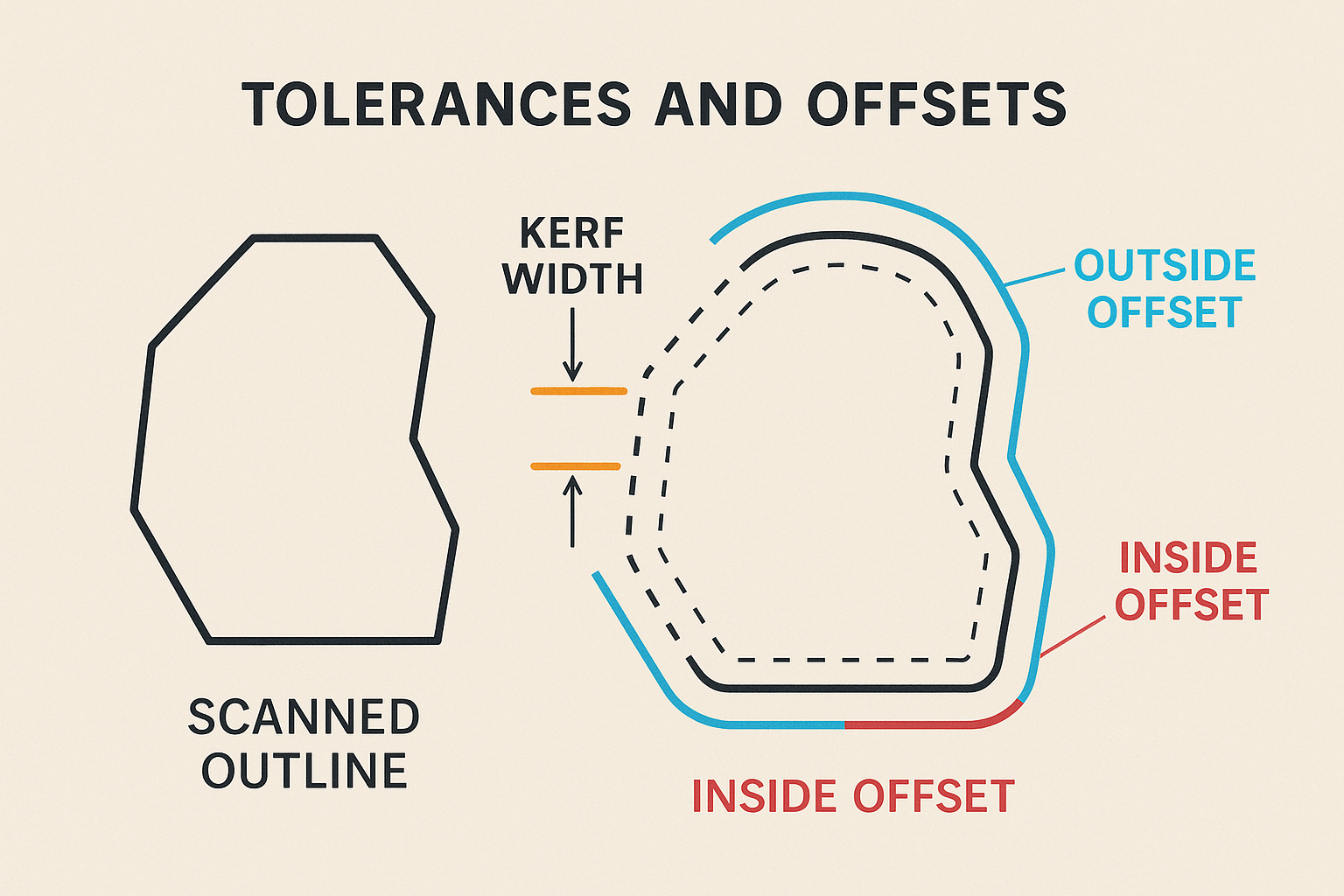
Kerf is the width of material removed by a cutting process.
- Laser cutters vaporise material → kerf depends on focus, power and material.
- CNC routers remove material with a spinning tool → kerf equals tool diameter.
- Waterjets and plasma cutters have their own kerf characteristics.
ShapeScan produces a centreline outline of the real object. The machine, however, removes material around that line.
Typical Kerf Values (Real-World)
| Process | Material | Typical Kerf |
|---|---|---|
| CO₂ Laser | 3mm plywood | 0.15 – 0.25 mm |
| CO₂ Laser | Acrylic | 0.10 – 0.20 mm |
| CNC Router | End mill Ø3mm | 3.00 mm |
| Desktop CNC | End mill Ø1mm | 1.00 mm |
Inside vs Outside Cuts: Why Direction Matters
Whether you offset inward or outward depends on what the outline represents.
Outer Contours
If the ShapeScan outline represents the outside of the object:
- Laser cutting → offset outwards by half the kerf.
- CNC routing → toolpath must be outside the contour.
Holes and Internal Cutouts
For holes and pockets:
- Laser cutting → offset inwards.
- CNC routing → toolpath inside the contour.
⚠️ Common Beginner Mistake
Applying the same offset direction to every path. Outer and inner contours always behave differently.
Tolerances: How Much Error Is Acceptable?
No physical process is perfect. Tolerance defines how much deviation you allow.
- Loose fit: +0.2 to +0.4 mm (easy assembly, visible gaps)
- Snug fit: +0.05 to +0.15 mm (most laser-cut parts)
- Press fit: 0 to −0.05 mm (material-dependent)
ShapeScan accuracy is typically higher than the cutting accuracy of hobby machines. That means tolerances are almost always driven by the machine, not the scan.
Workflow: ShapeScan to Laser Cutter
- Scan the original object with ShapeScan.
- Export SVG.
- Import into vector software (Illustrator, Inkscape, LightBurn).
- Apply kerf offset based on material and test cuts.
- Label inner and outer paths clearly.
- Run a small test before cutting the final part.
Workflow: ShapeScan to CNC Router
- Scan and export SVG or DXF.
- Import into CAM software.
- Select tool diameter.
- Assign inside/outside toolpaths.
- Set finishing pass for better accuracy.
- Measure first cut and adjust offsets if needed.
When to Modify the Scan vs Modify the Toolpath
A key principle:
- Never distort the scan to compensate for kerf.
- Always compensate in the manufacturing step.
The ShapeScan output should remain a true digital representation of the object. Offsets belong in CAM or cutting software.
Real-World Example: Replacing a Machine Bracket
You scan an old steel bracket to laser-cut a plywood prototype:
- Scan produces a 100% accurate outline.
- Laser kerf in plywood ≈ 0.2 mm.
- You offset outer contours by +0.1 mm.
- Holes are offset inward by −0.1 mm.
The resulting part fits the mounting points without forcing or slop.
Conclusion: Accuracy Is a Chain
ShapeScan gives you accurate geometry. Your machine introduces kerf. Tolerances define usability.
When you treat scanning, offsets and cutting as a single connected workflow, ShapeScan becomes not just a tracing tool, but a reliable bridge between the physical and digital worlds.