
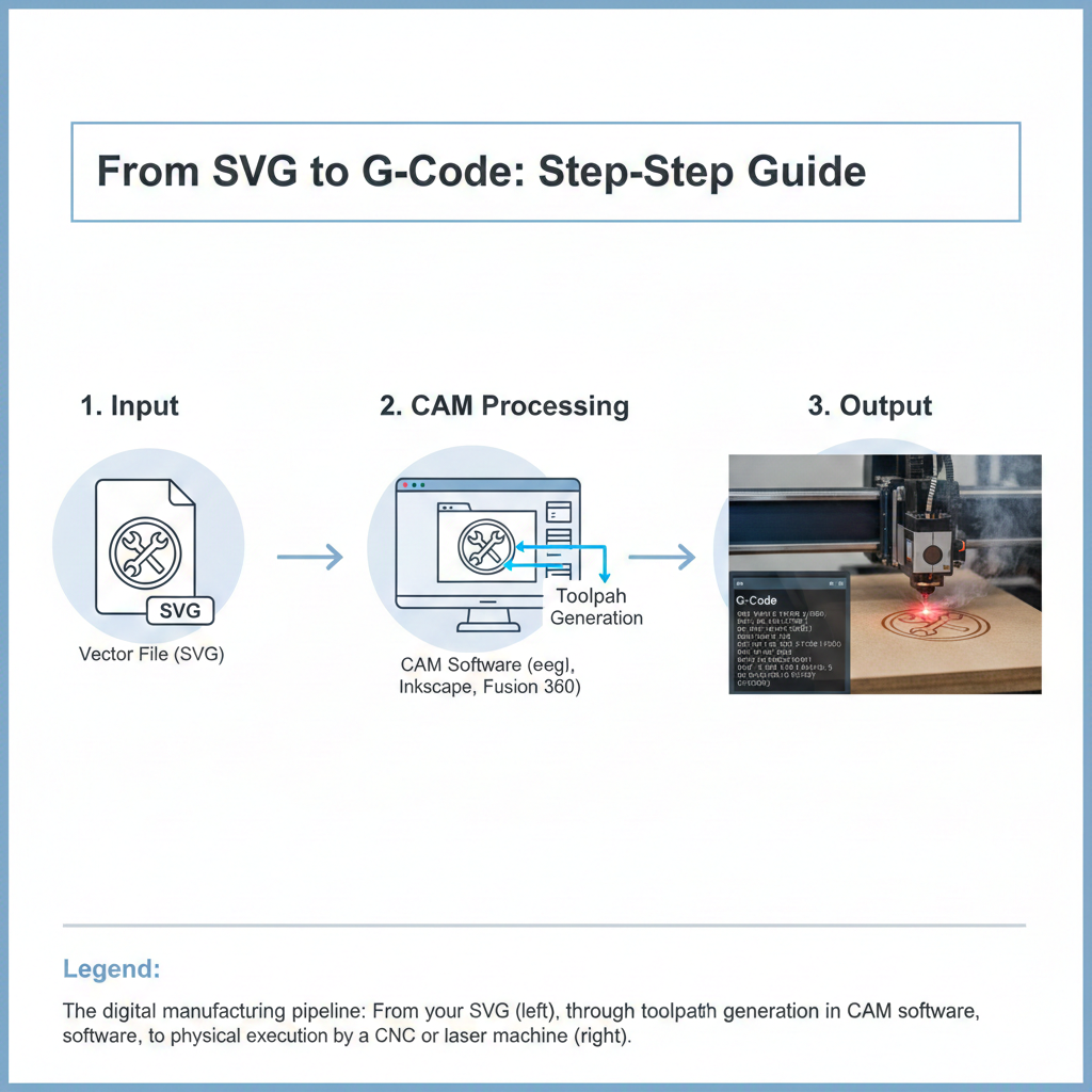
Creating a precise SVG file is only half the battle in digital fabrication. The real magic—and the biggest hurdle for many makers—is transforming that vector design into commands (G-Code) that a CNC or laser machine can understand and execute accurately. This guide details the complete process, from importing your ShapeScan SVG to the moment the machine starts cutting, covering the software, critical settings, and common pitfalls to avoid.
The Three-Step Manufacturing Pipeline
Every workflow, regardless of machine or software, follows this essential sequence:
Vector Preparation (SVG)
Ensure your file is "clean" and ready for CAM software.
Toolpath Generation (CAM)
Define how the machine will move to create your design.
Post-Processing & Machine Control
Translate toolpaths to your machine's specific language (G-Code) and send it.
Step 1: Preparing Your ShapeScan SVG for CAM
Before importing into any software, do a final check on your SVG. A well-prepared ShapeScan file should already meet most of these points, but it's good practice to verify.
✅ Pre-Import Checklist
- Closed Contours: All shapes should be closed paths. Open lines will cause CAM errors.
- No Duplicates: Overlapping lines can confuse software and cause double cuts.
- Correct Scale (MM): ShapeScan exports in real millimeters. Verify your software interprets units correctly.
- Clean Geometry: Remove any stray points or unnecessary elements outside your main design.
Step 2: CAM Software - Your Digital Machine Shop
Computer-Aided Manufacturing (CAM) software is the translator between your design and your machine. The choice depends on your machine type and budget.
| Software | Best For | SVG Import | Cost | Learning Curve |
|---|---|---|---|---|
| LightBurn | Laser cutters/engravers | Native support, excellent | $60 (one-time) | Low-Moderate |
| VCarve Pro | CNC routers (hobby to pro) | Direct import, good | $349-$699 | Moderate |
| Fusion 360 | Integrated CAD/CAM, CNC mills | Via "Canvas" or DXF | Free for hobbyists | Steep |
| Carbide Create | Carbide 3D CNC machines | Direct import | Free | Low |
| Inkscape + Extension | Basic laser/CNC (with plugins) | Native (it's a vector editor) | Free | Moderate |
Importing SVG into Popular CAM Software
LightBurn (Laser)
- File → Import your SVG
- Verify dimensions (mm/inches)
- Set cutting order (inside cuts first)
- Assign layer colors to different power/speed settings
VCarve (CNC Router)
- Set up your material size in new file
- Import Vectors from SVG file
- Check scale with measure tool
- Join/open vectors as needed
Fusion 360 (CAD/CAM)
- Create new sketch on desired plane
- Insert → Canvas and select SVG
- Scale canvas using known dimension
- Use Sketch → Project to create sketch geometry
Step 3: Toolpath Generation - The Critical Translation
Toolpaths are the calculated routes your machine's tool will follow. Different operations require different strategies.
Profile/Contour Cut
For: Cutting out shapes
Settings: Cut depth, inside/outside offset
CNC Tip: Use climb milling for better finish
Pocket Clearing
For: Removing material inside boundaries
Settings: Stepover (30-50%), multiple passes
Laser Tip: Equivalent to fill/engrave area
Drilling/Hole Making
For: Creating holes for fasteners
Settings: Peck drilling for deep holes
Both: Mark center first for alignment
Machine-Specific Parameters
| Parameter | CNC Router | Laser Cutter | ShapeScan Default |
|---|---|---|---|
| Feed Rate | 100-200 mm/sec (material dependent) | 10-100 mm/sec (power dependent) | N/A (Set in CAM) |
| Tool/Beam Diameter | 3-12mm (end mill size) | 0.1-0.3mm (laser kerf) | Offset tool in CAM |
| Pass Depth | 1-5mm per pass (material dependent) | Full thickness in 1 pass (or multiple for engraving) | N/A |
| Spindle Speed/Laser Power | 10,000-24,000 RPM | 20-100% power | N/A |
⚠️ Critical: Kerf Compensation
The Problem: Both CNC end mills and laser beams have thickness, removing material and making holes smaller/cuts larger than designed.
The Solution:
• CNC: Use CAM software's "tool offset" (typically ½ tool diameter)
• Laser: Use "kerf offset" in software (0.1-0.3mm usually)
• ShapeScan: Use "Contour offset" during export if you know your kerf
Step 4: G-Code - The Machine's Language
G-Code is the standardized but machine-specific language that tells your hardware exactly what to do.
Common G-Code Commands
G17        ; Select XY plane
G21        ; Units in millimeters
G90        ; Absolute positioning
G94        ; Units per minute feed rate

G0 X10 Y20 ; Rapid move to position
G1 X30 F100; Linear move at 100mm/min
G2/3       ; Clockwise/Counter-clockwise arc
M3/M4      ; Spindle/Laser on
M5         ; Spindle/Laser off
M30        ; Program end
Post-Processors: Machine-Specific Translation
A post-processor is a translator that converts generic toolpaths into G-Code your specific machine understands. Key considerations:
- Machine Controller: Grbl, Mach3, LinuxCNC, Smoothieware, proprietary
- Syntax Differences: Some use commas, others spaces between parameters
- Special Functions: Laser PWM control, spindle control, tool changes
- Always test new post-processors with safe, above-material moves first
Step 5: Simulation & Safety Checks
🔍 Visual Simulation
Run CAM software's simulator to check for:
• Tool collisions with material/hardware
• Missing or incorrect toolpaths
• Estimated machining time
📏 Manual Verification
Before cutting your final material:
1. Air Cut: Run program above material
2. Scrap Test: Cut cheap material first
3. Measure: Verify dimensions match SVG
⚠️ Emergency Preparedness
Know your machine's:
• Emergency stop button location
• Pause/resume procedure
• How to manually override feeds
Troubleshooting Common G-Code Issues
"Machine moves but doesn't cut"
Likely Cause: Spindle/laser not turned on in G-Code (missing M3/M4 command)
Fix: Check post-processor settings or add command manually
"Dimensions are wrong"
Likely Cause: Unit mismatch (mm vs inches) or missed kerf compensation
Fix: Verify G21 (mm) is in code header and tool diameter is correct
"Machine hits limits/stops abruptly"
Likely Cause: Program tries to move beyond machine travel or rapid moves too fast
Fix: Check material placement and reduce rapid (G0) feed rates
🎯 The ShapeScan to Machine Checklist
For a smooth workflow every time:
1. Scan: Get clean SVG from ShapeScan
2. Import: Check scale and clean geometry in CAM
3. Toolpath: Set feeds, speeds, and kerf compensation
4. Simulate: Visually verify in software
5. Post-Process: Generate machine-specific G-Code
6. Test: Air cut then scrap material test
7. Cut: Run final program on your material
Conclusion: From Digital to Physical
The path from SVG to finished part involves multiple software translations and careful parameter setting, but each step becomes routine with practice. Remember that ShapeScan provides the critical first link in this chain—a dimensionally accurate vector representation of your physical object. By mastering the subsequent CAM and G-Code generation process, you unlock the full potential of digital fabrication, turning ideas and scanned objects into precisely manufactured reality.
Pro Tip: Save your successful CAM settings as templates for different materials. Once you dial in parameters for "½ inch plywood" or "3mm acrylic," you can reuse them for future projects with consistent results.