
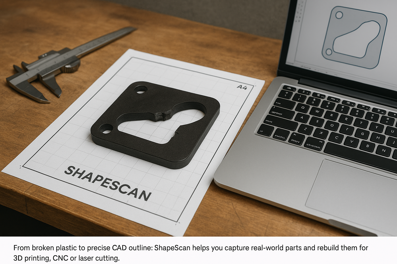
Most makers discover ShapeScan while designing new projects, but one of its most powerful uses is reverse engineering and repair. Instead of hunting for obscure spare parts or scrapping a tool because of a tiny broken bracket, you can photograph the original piece, trace it with ShapeScan and manufacture a replacement in your own workshop.
In this article we walk through a practical workflow for capturing broken or worn parts, turning them into useful geometry, and producing functional replacements with 3D printing, CNC machining or laser cutting.
Several flat parts to capture?
ShapeScan Premium v2.2 can separate multiple flat, non-overlapping objects placed on the marker sheet in one top-down photo. It is useful when you are documenting a batch of brackets, plates or workshop parts before modelling them. See Premium plans for Multi-object scanning.
The scan provides the 2D footprint. Measure thickness, threads, hidden geometry and other critical features separately before producing a final replacement.
Why Reverse Engineering with ShapeScan Works So Well
Traditional reverse engineering of small parts involves a lot of manual measuring: calipers, paper, hand-drawn sketches and a slow rebuild in CAD. ShapeScan removes most of this friction by using the A4 sheet as a reference:
- Automatic scaling: The A4 sheet gives a fixed size reference, so outlines are generated at true scale.
- Complex shapes captured quickly: Organic curves, fillets and unusual profiles are traced directly from the image.
- Fast iteration: If a detail is wrong, you can re-scan the part and update the outline in minutes.
- Cross-workflow friendly: The same ShapeScan output can feed a laser, CNC or 3D printer.
Typical Parts You Can Rebuild with ShapeScan
Appliance Brackets & Covers
Broken clips or covers from washing machines, dishwashers and vacuum cleaners are prime candidates.
Electronics Enclosures
Front panels, mounting plates and adapter plates for switches, screens or connectors.
Workshop Jigs & Inserts
Router templates, drill guides, tool organisers and custom foam or MDF inserts.
Automotive & Bike Bits
Plastic trim clips, spacer plates, gasket shapes and small mounting brackets.
Step 1: Capture the Original (Even When It’s Broken)
Ideally you scan a complete part, but in many repair situations you only have a damaged version. That’s fine: ShapeScan only needs a clear view of the geometry you want to keep.
- Assemble fragments if possible. For snapped parts, tape the pieces together on the A4 sheet so the original outline is restored.
- Scan in the working orientation. Place the surface you want to reproduce flat on the paper. If a part has several important faces, you can scan them one by one.
- Mark hidden or missing regions. Use a fine pen to sketch missing sections or symmetry lines directly on the sheet; ShapeScan will see these markings and you can trace over them later.
- Take multiple photos. Capture backups from slightly different positions so you can choose the cleanest one in ShapeScan.
🔁 Tip: Use Mirroring for Symmetrical Parts
If only one side of a symmetrical object is intact, scan the good half and mirror it in your CAD software. This is especially useful for handles, brackets and decorative trim pieces where left/right sides match.
Step 2: Clean Up the Outline in ShapeScan
After uploading the photo, ShapeScan generates one or more closed paths representing the part. At this stage you can simplify, adjust and prepare the geometry for manufacturing.
- Remove noise and stray shapes. Delete tiny islands or unwanted paths around shadows and background objects.
- Snap straight edges. For mechanical parts, use your CAD software later to enforce perfect lines and arcs, but try to keep the ShapeScan outline reasonably clean.
- Check critical dimensions. Measure between mounting holes or edges on the real part and compare with the ShapeScan dimensions. If needed, apply a very small global scale correction (for example 1–2%).
- Annotate features. You can export paths as SVG and add text or construction lines in your vector editor before importing into CAD or CAM tools.
Step 3: Bring the Outline into Your Design Tool
Once you are happy with the ShapeScan result, export it in the format that best matches your workflow:
- SVG/DXF for laser cutters and 2D CNC operations.
- SVG/DWG as a sketch reference in Fusion 360, FreeCAD or SolidWorks.
- PNG as a visual template in 3D sculpting tools or PCB design software.
In your CAD tool, you can now rebuild the part as a proper parametric model:
- Import the ShapeScan outline onto a sketch plane at 1:1 scale.
- Trace key edges with lines and arcs using the imported path as a guide.
- Add dimensions and constraints based on your caliper measurements.
- Extrude, shell or fillet the model to match the original thickness and shape.
Step 4: Choose the Right Manufacturing Method
With a finished model or vector file, you can choose how to build the replacement:
3D Printing
- Best for: Complex brackets, clips, functional prototypes.
- Materials: PETG, ABS or nylon for higher temperature and strength.
- Tip: Orient the part so layer lines support the mechanical loads.
Laser Cutting
- Best for: Flat profiles, gaskets, spacers, adapter plates.
- Materials: Acrylic, plywood, MDF, gasket sheet, thin aluminium (with suitable machine).
- Tip: Use ShapeScan’s outline directly as your cut path, adding mounting holes in your editor.
CNC Machining
- Best for: High-strength metal parts and precise mechanical components.
- Materials: Aluminium, steel, engineering plastics.
- Tip: Use the ShapeScan profile to define the outer contour, then add pockets and chamfers in CAM.
Step 5: Test, Iterate and Improve
The first version of a replacement part often reveals small differences that were not obvious in the scan: clearances that are too tight, hooks that need a bit more material, or areas that should be thicker.
- Dry-fit before full assembly. Test the part gently to see where it rubs, bends or interferes.
- Mark contact points. Use a pencil or marker to highlight regions that need adjustment.
- Update your model, not just the print. Each change should go back into the CAD file so you can re-use the design later.
- Save a “master” file. Store final STL, DXF and project notes together for future reprints.
⚠️ Safety and Responsibility
Reverse engineered parts are fantastic for non-critical components, but use caution when repairing anything related to high voltage, pressure, fuel, brakes or life-safety systems. In those cases, always follow the manufacturer’s recommendations and local regulations.
Real-World Example: Vacuum Cleaner Hose Adapter
A classic ShapeScan repair is the broken hose adapter on a shop vacuum. These parts are often discontinued, but their geometry is simple and perfect for scanning:
- Scan the broken adapter end on an A4 sheet using ShapeScan.
- Export the outline and revolve it in CAD to build a 3D model.
- Measure the mating hose and tool diameters, add tolerances and small fillets.
- 3D print in PETG with thick walls for durability.
- Test fit, adjust once if needed, then save the design for future use.
What used to be an annoying hunt for a spare part becomes a repeatable digital asset you can print as many times as you like.
Conclusion: Turn Broken Parts into Opportunities
Reverse engineering with ShapeScan is not just about fixing things cheaply; it is about building a personal library of custom components. Every time you repair a bracket, spacer or panel using this workflow, you add another proven design to your toolbox.
Next time something breaks, do not throw it away immediately. Drop it on an A4 sheet, take a ShapeScan, and see how quickly you can turn “impossible to source” into “print another one”.