
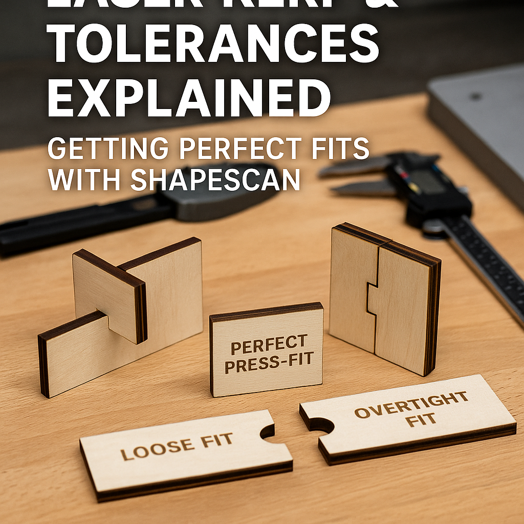
If you have ever designed a part that looked perfect on screen but came out too loose (or too tight) on the laser cutter, you have already met kerf and manufacturing tolerances.
ShapeScan generates accurate, real-scale outlines, but laser cutting is a subtractive process: material is removed. To get truly precise results, you must understand how kerf works and how to compensate for it in your workflow.
What Is Laser Kerf?
Kerf is the width of material removed by the laser beam during cutting. Even though a laser looks like a thin line of light, it always has a measurable width.
- Typical CO₂ laser kerf: 0.10–0.25 mm
- Depends on: lens, focus, material, power and speed
- Applies on both sides of a cut path
This means that a 10.00 mm slot cut with a 0.20 mm kerf will actually measure around 10.20 mm if no compensation is applied.
Why Kerf Matters When Using ShapeScan
ShapeScan captures the real geometry of your part at true scale. That is exactly what you want — but it also means the exported outline represents the ideal shape, not the manufacturing reality.
Without kerf compensation, this often results in:
- Press-fit joints that slide apart
- Tabs that wobble inside slots
- Stacked layers that drift out of alignment
- Assemblies that require glue when they should not
Common Laser Cutting Tolerance Scenarios
Loose Fit
Parts slide together easily, but lack friction or structural strength. Usually caused by ignoring kerf entirely.
Overtight Fit
Parts require hammering or snap during assembly. Often caused by double compensation or incorrect material thickness assumptions.
Perfect Press-Fit
Parts slide together firmly by hand and stay locked without glue. This is the result of correct kerf measurement and consistent material choice.
Step 1: Measure Your Laser Kerf
Never rely on theoretical values. Always measure kerf on your machine.
- Design a simple rectangle, e.g. 50.00 mm wide.
- Cut it from your target material.
- Measure the result with calipers.
- Kerf = (measured size − design size).
📏 Example Kerf Measurement
Designed width: 50.00 mm
Measured width: 50.22 mm
Kerf = 0.22 mm
Step 2: Decide Where to Apply Kerf Compensation
There are three common places to compensate for kerf:
Inside Your CAD Software
- Adjust slot widths manually
- Best for parametric designs
- Most control, more setup time
Inside CAM / Laser Software
- Offset paths automatically
- Fast and flexible
- Requires consistent machine settings
Directly in ShapeScan
ShapeScan allows uniform outline offsets, which is ideal for:
- Flat press-fit parts
- Gaskets and spacers
- Laser-cut jigs and fixtures
Recommended Workflow with ShapeScan
- Scan the part and generate the outline at true scale.
- Export as SVG or DXF.
- Apply a negative offset of half the kerf for outer contours.
- Apply a positive offset of half the kerf for slots and holes.
- Cut a small test piece before committing to full production.
Material Matters: Kerf Is Not Universal
Kerf changes with material. Never assume one value fits everything.
- 3 mm plywood: often inconsistent due to glue layers
- MDF: very predictable kerf
- Acrylic: clean kerf but sensitive to focus height
- Leather & fabric: kerf varies with speed and power
Advanced Tip: Tolerance Stacking
When multiple laser-cut parts assemble together, small errors add up. This is called tolerance stacking.
In these cases:
- Favor slightly tighter fits on non-critical joints
- Leave clearance on long alignment features
- Test assemblies in sections, not only as a whole
Conclusion: Shape Accuracy + Process Knowledge
ShapeScan gives you accurate geometry. Laser cutting introduces real-world physics. When you combine both, you get professional results.
By measuring kerf, applying consistent offsets and testing smartly, you can turn scanned outlines into assemblies that fit perfectly straight off the laser bed.