
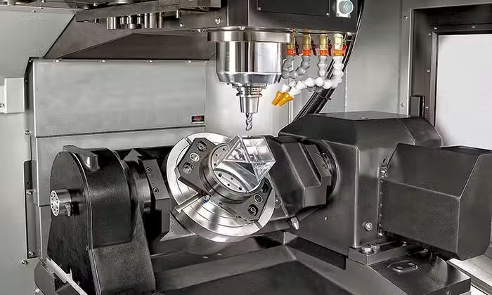
Computer Numerical Control (CNC) machining transforms digital designs into physical parts with precision unattainable by manual methods. This article details how ShapeScan's dimensionally-accurate vector outputs integrate directly into professional CNC workflows—from hobbyist routers to industrial mills—bridging the gap between physical objects and G-code.
The CNC Advantage: Why Vectors Beat Manual Measurement
Traditional methods for replicating physical objects in CNC involve:
- Manual tracing with calipers: Time-consuming (30+ minutes for complex shapes) with accumulated error (±0.5-1mm typical).
- 3D scanning: Expensive ($500-$5000+), overkill for 2.5D machining, often requires post-processing.
- Photogrammetry apps: Produce raster images requiring manual vectorization in Illustrator/Inkscape.
ShapeScan delivers ready-to-machine vectors in under 2 minutes with ±0.3mm accuracy—directly addressing the "measurement bottleneck" in custom fabrication.
Workflow: Photo → DXF → CAM → G-code
The optimal pipeline for CNC fabrication:
📸 1. Scanning for CNC-Specific Considerations
Photography: Place object on marker sheet with machining reference edge aligned to sheet border. This establishes natural X/Y axes for CAM.
Settings: Use 12 px/mm resolution for fine details (inlays, gears). Set contour offset to +0.0mm initially—add machining allowances in CAM, not scanning.
Holes & Cutouts: Enable "Keep internal holes" for bolt patterns, vents, or decorative cutouts.
🖥️ 2. DXF Import & CAD Preparation
Importing to CAD/CAM: ShapeScan's DXF uses real-world millimeters, importing at 1:1 scale in Fusion 360, VCarve, Carbide Create, or AutoCAD.
Common fixes:
- Closed contours: Verify all paths are closed (no gaps) using CAD's "Join" or "Weld" commands.
- Duplicate lines: Some CAM software may duplicate vectors; use "Remove Overlaps" or "Weld Vectors."
- Nesting: Copy and arrange multiple instances for batch machining.
Toolpath Strategies by Material & Machine
| Material | Recommended Tool | Feed Rate | ShapeScan Offset | CAM Strategy |
|---|---|---|---|---|
| Hardwood | ¼" 2-flute upcut | 100-150 ipm | +0.0 mm | Profile cut (outside) + pocketing |
| Plywood/MDF | ⅜" compression | 150-200 ipm | +0.1 mm | Single profile pass (kerf allowance) |
| Acrylic/Polycarbonate | ⅛" single flute | 60-80 ipm | -0.05 mm | Climb cutting for clear edges |
| Aluminum (soft) | ¼" 3-flute carbide | 40-60 ipm | +0.0 mm | Adaptive clearing + finishing pass |
| Foam (tooling) | ½" ball nose | 200-300 ipm | +0.3 mm | 3D contour following |
Advanced Techniques: Fixtures, Tolerances & Multi-Part Assemblies
1. Scanning for Custom Fixtures & Jigs
Problem: Creating a vacuum fixture or custom vise jaw for irregular parts.
Solution:
- Scan the part's footprint with "Keep holes" enabled.
- Import DXF into CAD and offset contour by -2mm to create recess.
- Add vacuum channels or mounting holes using the scanned geometry as reference.
- Machine fixture from UHMW or aluminum.
Accuracy: ±0.2mm fit ensures part stability during machining.
2. Press-Fit & Interference Fits
For parts that snap together (dovetails, finger joints, inserts):
- Scan both mating parts separately on the same sheet to ensure consistent scale.
- In CAM, apply different offsets:
- Male part: -0.1mm (slightly smaller)
- Female part: +0.0mm (exact size)
- Test in soft material first (MDF) before machining final material.
⚙️ Case Study: Replacing a Broken Machine Guard
Problem: Broken acrylic guard on vintage equipment with no CAD files available.
Solution:
1. Scan remaining fragments arranged on marker sheet.
2. Use ShapeScan editor to connect broken edges into complete profile.
3. Export DXF and import into CAM software.
4. Machine replacement from 6mm polycarbonate with bolt holes positioned from scan.
5. Install - perfect fit with original mounting points.
Time saved: 4 hours vs. manual measurement & CAD recreation.
Integrating with Popular CAM Software
Fusion 360
- Import DXF via "Insert → Canvas"
- Use "Sketch → Project" for toolpaths
- Best for: 2.5D adaptive clearing
VCarve/Aspire
- Direct DXF import
- Built-in nesting optimization
- Best for: Signmaking, woodworking
Carbide Create
- Import at 1:1 scale
- Simple 2D toolpath generation
- Best for: Hobbyist CNC routers
SheetCam
- Optimized for plasma/laser
- Lead-in/out automation
- Best for: Metal fabrication
Material-Specific Machining Adjustments
| Consideration | Wood | Plastics | Aluminum | Composite |
|---|---|---|---|---|
| Kerf Compensation | +0.1-0.2mm | +0.05-0.1mm | +0.0-0.05mm | +0.1-0.15mm |
| Tool Wear | Minimal | Moderate (melting) | Significant | Severe (abrasive) |
| Hold-Down Method | Clamps/screws | Vacuum tape | Vise/bolts | Double-sided tape |
| Scan Resolution Needed | 8 px/mm | 10 px/mm | 12 px/mm | 8 px/mm |
Troubleshooting Common CNC Issues
🔍 Parts Don't Fit Together
Cause: Accumulated error from scan + CAM + machine deflection.
Fix: Scan both parts together on same sheet. Apply uniform scaling in CAM (99.5% if too tight).
📏 Dimensions Don't Match Scan
Cause: Incorrect units (mm vs inches) during CAM import.
Fix: Verify DXF imports at 1:1 mm. Check machine steps/mm calibration.
⚙️ Jagged Edges on Curves
Cause: Low scan resolution or excessive simplification.
Fix: Rescan at 12+ px/mm with 0.1mm simplification. Use smaller tool (⅛" vs ¼").
Beyond 2.5D: Extending to 3D Machining
While ShapeScan excels at 2D profiles, it enables 3D machining through:
- Multi-layer scanning: Scan object at different heights (using spacers), creating stacked contours for 3D roughing.
- 4th-axis rotary: Scan cylindrical object profile for rotary machining (handles, knobs).
- Texture mapping: Use scanned outline as displacement map for 3D surfacing (carvings, reliefs).
🏭 Production Workflow: Batch Scanning for Small Manufacturing
Scenario: Small shop producing custom guitar picks from customer-provided designs.
Traditional: Manual vectorization @ 15 mins/pick = 4 hours/day.
With ShapeScan:
1. Arrange 20-30 designs on single marker sheet.
2. Single photo scan with "Keep holes" for center cutouts.
3. Batch process in ShapeScan (automated via API in development).
4. Import DXF into CAM with automatic nesting.
5. Machine 200+ picks/hour from acrylic sheets.
Efficiency gain: 90% time reduction in design-to-G-code phase.
Conclusion: The Digital Fabrication Bridge
ShapeScan eliminates the most tedious aspect of CNC workflows—manual measurement and vectorization—while maintaining the precision required for professional fabrication. By transforming smartphone photos into machine-ready vectors in minutes rather than hours, it makes custom CNC work accessible to:
- Small manufacturers: Rapid prototyping and short-run production
- Makers & hobbyists: Custom parts without CAD expertise
- Repair technicians: Reverse engineering discontinued parts
- Artists & designers: Converting physical art into machinable designs
The combination of accessibility (any smartphone), precision (±0.3mm), and integration (direct DXF export) positions ShapeScan as a critical tool in the modern digital fabrication toolkit—proving that sometimes the most advanced solutions are those that simply remove barriers between the physical and digital worlds.